
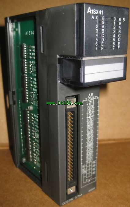
A1SX41 MITSUBISHI A1SX41
Brand:
MITSUBISHI
Name: DC leakage type input module
Model: A1SX41
Type of input: DC leakage.
Input points: 32 points.
Input voltage: 12/24.
Input current: 3/7mA.
Connection mode: terminal row.
Common common point: 32.
Functional block diagram language is a kind of PLC programming language, which is similar to digital logic circuit.
The function module is used to represent the function of the module,
Different function modules have different functions.
Functional module figure programming language features: functional block diagram programming language is characterized by a functional module for the unit,
Analysis and understanding of the control scheme is simple and easy: function module is to use graphical form of expression,
Intuitive, for a digital logic circuit based on the design of the staff is very easy to master the programming;
Control system with complex scale and complex control logic,
Because the function module diagram can clearly express the function relation, the programming debugging time is greatly reduced.
...More relevant models >>>>
Name: DC leakage type input module
Model: A1SX41
Type of input: DC leakage.
Input points: 32 points.
Input voltage: 12/24.
Input current: 3/7mA.
Connection mode: terminal row.
Common common point: 32.
Functional block diagram language is a kind of PLC programming language, which is similar to digital logic circuit.
The function module is used to represent the function of the module,
Different function modules have different functions.
Functional module figure programming language features: functional block diagram programming language is characterized by a functional module for the unit,
Analysis and understanding of the control scheme is simple and easy: function module is to use graphical form of expression,
Intuitive, for a digital logic circuit based on the design of the staff is very easy to master the programming;
Control system with complex scale and complex control logic,
Because the function module diagram can clearly express the function relation, the programming debugging time is greatly reduced.
Input: AC100 ~ 120V/200 ~ 240V,
Output: 3A/DC24V 0.6A DC5V.
PLC programming has a wide range of applications, powerful, easy to use, has become one of the main devices of modern industrial automation,
In all areas of industrial production has been widely used,
Applications in other areas (such as civil and home automation) have also been rapidly developed MITSUBISHI A1SX41.
It uses programmable memory,
An instruction used to perform logical operations, sequence control, timing, counting and arithmetic operations in its internal storage,
And through digital, analog input and output,
Control of various types of machinery or production processes A1SX41 Programmable controller and related equipment,
Should be easy to make the industrial control system to form a whole, easy to expand the principle design of its functions MITSUBISHI A1SX41.
As can be seen from the above definition, PLC is a program to change the control function of the industrial control computer,
In addition to the completion of a wide variety of control functions, as well as with other computer communications networking features. Input channel number: 2.
Output channel number: 1 MITSUBISHI A1SX41.
Occupy I/O points: 32.
A1S63ADA analog input / output combination components can be analog / digital / digital / analog conversion,
The input and output signals can be voltage or current,
Offset and gain can be set and stored.
The length of time required to execute the instruction, the length of the user''s program, the type of instruction, and the speed of the CPU execution are very significant,
Generally, a scanning process, the fault diagnosis time,
Communication time, input sampling and output refresh time is less,
The execution time is accounted for the vast majority of MITSUBISHI DC leakage type input module MITSUBISHI DC leakage type input module.
The response time of PLC is the interval between the time of the change of the external output signal of the PLC and the time of the change of the external output signal which is controlled by it,
Lag time, this is the time constant of the input circuit,
The time constant of the output circuit, the arrangement of the user statement and the use of the instruction,
The cycle scan mode of PLC and the way of PLC to refresh the I/O and so on MITSUBISHI DC leakage type input module.
This phenomenon is called the I/O delay time effect. 3C-2V/5C-2V coaxial cable between the single bus PC network (control station / common station) / remote I/O network (remote master).
Q mode.
When the programmer input programinto the user program memory,
Then CPU according to the function of the system (the system program memory to explain the compiler),
Translate the user program into PLC internally recognized by the user to compile the program.
Input status and input information input from the input interface,
CPU will be stored in the working data memory or in the input image register.
And then combine the data and the program with CPU.
The result is stored in the output image register or the working data memory,
And then output to the output interface, control the external drive.
Semiconductor circuit with memory function.
System program memory and user memory.
System program memory for storing system program,
Including management procedures, monitoring procedures, as well as the user prograam to do the compiler to compile the process of interpretation A1SX41.
Read only memory. Manufacturers use, content can not be changed, power does not disappear.
User memory: user program storage area and work data storage area.
Composed of random access memory (RAM) MITSUBISHI A1SX41. User use.
Power cut off. Commonly used efficient lithium battery as a backup power supply, life is generally 3~5 years.
...More relevant models >>>>
 Last one: MITSUBISHI Input module A1SX40-S2
 next one: MITSUBISHI DC leakage type input module A1SX41-S2
Related download