
Home
>> Products
>> MITSUBISHI
>> A/QnA series PLC
>> CPU
>> A0J2CPU-DC24-S2 MITSUBISHI CPU unit MITSUBISHI A0J2CPU-DC24-S2
A0J2CPU-DC24-S2 MITSUBISHI CPU unit MITSUBISHI A0J2CPU-DC24-S2
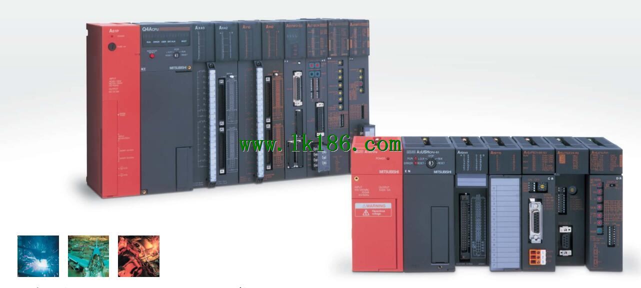
Brand:
MITSUBISHI
Name: CPU unit
Model: A0J2CPU-DC24-S2
Input and output points: 480 points.
Program capacity: 7K step.
Basic command processing speed: 4.4 ~ 5.6us.
Power supply: input DC5V output 2A DC24V/.
Modular: PLC is the basic components of a separate module.
Medium and large PLC used this way. Easy maintenance.
Relay output interface circuit of PLC
Working process: when the internal circuit output digital signal 1,
There is a current flowing through, the relay coil has a current, and then the normally open contact is closed,
Provide load current and voltage.
When the internal circuit outputs a digital signal 0, there is no current flowing through it,
The relay coil does not have a current, and the normally open contact is broken off,
A current or voltage that is disconnected from the load.
It is through the output interface circuit to the internal digital circuit into a signal to make the load action or not action.
User program storage capacity: it is a measure of how much the user application can store the number of indicators.
Usually in words or K words as units. 16 bit binary number is a word,
Every 1024 words are 1K words. PLC to store instructions and data in words.
General logical operation instructions each account for 1 words. Timer / counter,
Shift instruction accounted for 2 words. Data operation instructions for 2~4.
...More relevant models >>>>
Name: CPU unit
Model: A0J2CPU-DC24-S2
Input and output points: 480 points.
Program capacity: 7K step.
Basic command processing speed: 4.4 ~ 5.6us.
Power supply: input DC5V output 2A DC24V/.
Modular: PLC is the basic components of a separate module.
Medium and large PLC used this way. Easy maintenance.
Relay output interface circuit of PLC
Working process: when the internal circuit output digital signal 1,
There is a current flowing through, the relay coil has a current, and then the normally open contact is closed,
Provide load current and voltage.
When the internal circuit outputs a digital signal 0, there is no current flowing through it,
The relay coil does not have a current, and the normally open contact is broken off,
A current or voltage that is disconnected from the load.
It is through the output interface circuit to the internal digital circuit into a signal to make the load action or not action.
User program storage capacity: it is a measure of how much the user application can store the number of indicators.
Usually in words or K words as units. 16 bit binary number is a word,
Every 1024 words are 1K words. PLC to store instructions and data in words.
General logical operation instructions each account for 1 words. Timer / counter,
Shift instruction accounted for 2 words. Data operation instructions for 2~4.
SI-200/250 fiber optic cable.
Double loop.
Remote station.
According to the control requirements of the system, using the appropriate design method to design MITSUBISHI PLC program.
Procedures to meet the requirements of system control as the main line,
Write one by one to achieve the control function or the sub task of the program,
Gradually improve the functions specified by the system MITSUBISHI A0J2CPU-DC24-S2 A0J2CPU-DC24-S2
MITSUBISHI PLC initialization procedure. After MITSUBISHI PLC on power, the general need to do some of the initial operation,
In order to start making necessary preparations, to avoid the wrong operation of the system.
The main contents of the initialization program are: to some data area, counter and so on,
Data needed to restore some of the data area,
Set or reset some relays,
For some initial state display, etc MITSUBISHI A0J2CPU-DC24-S2. . Input points: 32 points.
Input voltage and current: 3/7mA DC12/24V.
Input response time: 10ms.
16 point /1 a public side.
Output points: 24 points.
Output voltage: AC100 ~ 240V.
OFF leakage current: 3mA.
Output response time: 0.5Hz+1ms.
Output type: bidirectional thyristor output.
36 point terminal station MITSUBISHI A0J2CPU-DC24-S2.
With short circuit protection.
With the surge absorber.
Control solenoid valve required I/O points by the action principle of the solenoid valve can be known,
A single coil solenoid valve with PLC control to 2 input and 1 output,
A double coil solenoid valve requires 3 inputs and 2 outputs,
A button needs an input; a light sensitive switch needs 4 or 2 inputs,
A signal lamp needs 1 output, band switch,
Several bands are required for several inputs,
In general, a variety of position switches are required to take up 2 input points MITSUBISHI CPU unit MITSUBISHI CPU unit.
MITSUBISHI PLC is the main product in the production of MITSUBISHI motor in Dalian.
It uses a kind of programmable memory for its internal storage procedures,
Execute logic operation, sequence control, timing, counting and arithmetic operations, user oriented instruction,
And through digital or analog input / output control of various types of machinery or production process MITSUBISHI CPU unit.
The number of I/O thyristor DC motor control required tube DC motor speed control system is the main form of DC speed regulation,
The thyristor rectifier unit is used to supply power to the DC motor.
PLC control of the DC drive system, the input of the PLC in addition to the main signal outside the signal,
We need to consider the switching signal, the fault signal transmission device, braake signal and fan fault signal A0J2CPU-DC24-S2.
The output of the PLC mainly consider the speed command signal positive 1~3 level, 1~3 level, allowing reverse switching signal and brake open signal etc..
In general, a reversible DC drivee system controlled by PLC is approximately 12 input points and 8 output points,
An irreversible DC drive system requires 9 inputs and 6 output points MITSUBISHI A0J2CPU-DC24-S2.
...More relevant models >>>>
 Last one:
  next one:
 Related download