
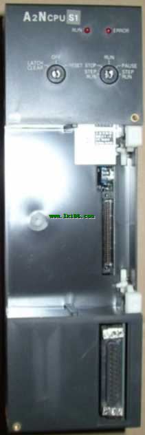
MITSUBISHI A2NCPU-S1 CPU unit A2NCPU-S1
Type of input: DC source.
Input points: 32 points.
Input voltage: DC24.
Input current: 7mA.
Connection mode: terminal row.
Common common point: 32.
Sequential function flow chart language is designed to satisfy the sequential logic control.
The process of sequential process action is divided into steps and transformation conditions,
Accorrding to the transfer condition, the control system is distributed in the function flow sequence,
Step by step according to the sequence of actions A2NCPU-S1 A2NCPU-S1.
Each step represents a control function, represented by the box.
In the box, the ladder logic is used to complete the task of the corresponding control function.
This programming language makes the program structure clear and easy to read and maintain,
Greatly reduce the programming workload, shorten the programming and debugging time A2NCPU-S1.
Used in the system of the size of the school, procedures for more complex occasions.
Sequence function flow chart programming language features: to function as the main line, in accordance with the functional flow of the order of distribution, clear, easy to understand the user program,
Avoid the defect of ladder diagram or other languages,
At the same time, the use of ladder language to avoid the use of ladder programming,
Due to the complicated mechanical interlock, the structure of the user program is complex and difficult to understand,
User program scan time is also greatly reduced MITSUBISHI A2NCPU-S1 MITSUBISHI A2NCPU-S1. SI-200/250 fiber optic cable.
Double loop.
MELSECNET (II) (remote I/O station).
According to the control requirements of the system, using the appropriate design method to design MITSUBISHI PLC program MITSUBISHI A2NCPU-S1.
Procedures to meet the requirements of system control as the main line,
Write one by one to achieve the control function or the sub task of the program,
Gradually improve the functions specified by the system.
MITSUBISHI PLC initialization procedure. After MITSUBISHI PLC on power, the general need to do some of the initial operation,
In order to start making necessary preparations, to avoid the wrong operation of the system.
The main contents of the initialization program are: to some data area, counter and so on,
Data needed to restore some of the data area,
Set or reset some relays,
For some initial state display, etc..
Input and output points: 1024 points.
Input / output data points: 1024 points.
Program capacity: 14K.
Basic command processing speed (LD command) s:1.0.
AnNCPU command processing time and ACPU compare to 10-20% high speed processing.
User program storage capacity: it is a measure of how much the user application can store the number of indicators.
Usually in words or K words as units. 16 bit binary number is a word,
Every 1024 words are 1K words. PLC to store instructions and data in words.
General logical operation instructions each account for 1 words. Timer / counter,
Shift instruction accounted for 2 words. Data operation instructions for 2~4.
Integral type: the PLC components are installed together or a few pieces of printed circuit board,
And together with the power supply iinstalled in the casing to form a single overall called the host or the basic unit, small, ultra small PLC using this structure A2NCPU-S1.
Modular: PLC is the basic components of a separate module.
Medium and large PLC used this way. Easy maintenance.