
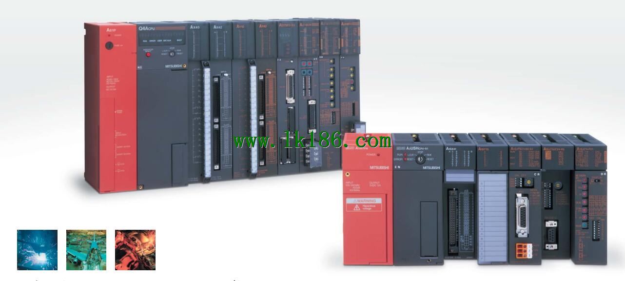
AD71-S1 MITSUBISHI AD71-S1
32 point connector for compression connector (40 pin connector.DC input points: 4 points.
Input voltage and current: 7mA, DC24V.
Input response time: 10ms.
4 point /1 a public side.
Positive pole sharing.
Output points: 4 points.
Output voltage and current: DC24V.
Output response time: 2ms AD71-S1.
4 point /1 a public side.
Output fform: transistor output, leakage type.
24 point terminal station.
MITSUBISHI PLC protection and chain procedures.
Protection and chain is an indispensable part of the program, must be carefully considered AD71-S1.
It can avoid the control logic confusion caused by illegal operations.
MITSUBISHI PLC initialization procedure. After MITSUBISHI PLC on power, the general need to do some of the initial operation,
In order to start making necessary preparations, to avoid the wrong operation of the system AD71-S1.
The main contents of the initialization program are: to some data area, counter and so on,
Data needed to restore some of the data area,
Set or reset some relays,
For some initial state display, etc..
MITSUBISHI PLC program simulation debugging
The basic idea of program simulation debugging is,
In order to facilitate the form of simulation to generate the actual state of the scene,
Create the necessary environmental conditions for the operation of the program MITSUBISHI AD71-S1.
Depending on the way the field signals are generated,
The simulation debugging has two forms of hardware simulation and software simulation MITSUBISHI AD71-S1.
2 axes.
2 axis linear interpolation.
Control unit: pulse, mm, inch, degree.
Determine the location of the number of data: 400/1 axis.
40 pin connector MITSUBISHI AD71-S1.
Control mode: position automatic acceleration and deceleration time: 64-4999ms pulse train output DC servo MELDAS-S1 with work output.
The working process of the input interface circuit: when the switch is closed, the diode light,
The transistor is then guided to the internal circuit and input signal under the irradiation of the light.
When the switch is off, the diode does not emit light, and the transistor is not on the way. Internal circuit input signal.
It is through the input interface circuit to the external switch signal into PLC internal can accept the digital signal.
PLC selection with the development of PLC technology, more and more types of PLC products,
Function is becoming more and more perfect, and its application is more and more extensive.
Different series of different models of PLC has different performance, applicable occasions also have different emphasis,
Price also has a greater difference. Therefore PLC selection,
Under the premise of meeting the control requirements,
Should consider the best performance to price ratio, a reasonable choice of PLC.
Input status and input information input from the input interface,
CPU will be stored in the working data memory or in the input image register.
And then combine the data and the program with CPU.
The result is stored in the output image register or the working data memory,
And then output to the output interface, control the external drive.
MITSUBISHI PLC is the main product in the production of MITSUBISHI motor in Dalian.
It uses a kind of programmable memory for its internall storage procedures,
Execute logic operation, sequence control, timing, counting and arithmetic operations, user oriented instruction,
And through digital or analog input / output control of various types of machinery or production process AD71-S1.