
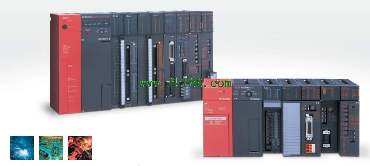
MITSUBISHI A2ACPUP21-S3 Input / output data points: 512 pointsMITSUBISHI A2ACPUP21-S3
Output points: 8 points.
Output voltage and current: AC100 ~ 240V, 0.6A/1 point, 4A/1 public end.
Response time: 0.5Hz+1ms.
Output form: bidirectional thyristor output.
8 point /1 a public side.
26 point terminal station.
Number of stations: 1 stops.
Type remote I/O units outside of the panel (optical data connection) A2ACPUP21-S3.
Equuipment layer / field bus CC-Link device layer is the PLC and other control devices and sensors and drive devices connected to the field network,
Network for the lowest layer of the whole network system A2ACPUP21-S3.
Using CC-Link field bus connection, the number of wiring is greatly reduced,
Improve the maintainability of the system.
And, not just the amount of data ON/OFF and other switches,
Can also be connected to the ID system, bar code reader, inverter, man-machine interface and other intelligent devices,
From the completion of a variety of data communication, the management of the terminal production information can be realized,
On the centralized management of the state of the machine movement,
Make maintenance work efficiency also greatly improved A2ACPUP21-S3 MITSUBISHI A2ACPUP21-S3.
Q series PLC in the use of CC-Link function better,
And easier to use.
Mitsubishi Co PLC network inherited the traditional use of the MELSEC network,
And make it better in terms of performance, function, easy to use etc..
Provides a layer of three layers of clear network, to provide the most suitable network products for a variety of uses MITSUBISHI A2ACPUP21-S3.
The information layer /Ethernet (Ethernet) information layer is the highest level of the network system,
Mainly in the PLC, the device controller and production management with PC transmission between production management information, quality management information and the operation of equipment, etc MITSUBISHI A2ACPUP21-S3.,
Information layer using the most common Ethernet.
It is not only able to connect the PC system UNIX, windows system, etc.,
And can connect a variety of FA devices.
The Ethernet module has the function of Internet e-mail receiving and sending,
The user can send and receive the production information conveniently in any place of the world,
Build a remote monitoring management system.
At the same time, the use of the Internet FTP server functions and MELSEC protocol can be very easy to achieve the program upload / download and transfer of information. Input type: DC input, positive common end.
Input points: 16 points.
Enter the response time: 1.5ms the following.
Rated input voltage / current: DC24V/5mA.
External connection: 3 wire.
Spring clip terminal.
Do not need to be tightened further or locked with screws, which can reduce the working hours of wiring.
Using 2 pieces of structure of the terminal units, maintenance can be maintained in the same line under the condition of the replacement module.
When installing the module can choose to use the DIN guide rail or screw mounting.
Can be used for the 3 wire sensor input wiring.
Input and output points: 512 points.
Input / output data points: 512 points.
Program capacity: 14K.
Basic command processing speed (LD command) s:0.20.
Optical data communication line function (GI cable).
Integral type: the PLC components are installed together or a few pieces of printed circuit board,
And together with the power supply installed in the casing to form a single overall called the host or the basic unit, small, ultra small PLC using this structure.
Modular: PLC is the basic components of a separate module.
Medium and large PLC used this way. Easy maintenance.
Each scanning process. Focus on the input signal sampling. Focus on the output signal to refresh.
Input refresh process. When the input port is closed,
Program in the implementation phase, the input end of a new state, the new state can not be read.
Only when the program is scanned, the new state is read.
A scan cycle is divided into the input sample, the program execution, the output refresh.
The contents of the component image register are changed with the change of the execution of the program.
The length of the scan cycle is determined by the three.
CPU the speed of executing instructions.
Time of instruction.
Instruction count.
Due to the adoption of centralized sampling.
Centralized output mode.
There exist input / output hysteresis phenomena, i.e., the input / output response delay.
User program storage capacity: it is a measure of how much the user application can store the number of indicators.
Usually in words or K words as units. 16 bit binary number is a word,<
Every 1024 words are 1K words A2ACPUP21-S3. PLC to store instructions and data in words.
General logical operation instructions each account for 1 words. Timer / counter,
Shift instruction accounted for 2 words. Data operation instructions for 2~4.