
AJ71C24-S3 MITSUBISHI AJ71C24-S3
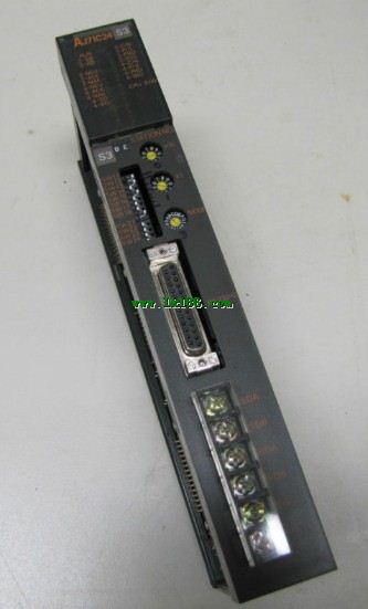
Module for A3VTS multiplex system.
MITSUBISHI PLC detection, fault diagnosis and display and other procedures.
These procedures are relatively independent, generally in the basic completion of the program design and then add.
MITSUBISHI PLC protection and chain procedures.
Protection and chain is an indispensable part of the program, must be carefully considered AJ71C224-S3.
It can avoid the control logic confusion caused by illegal operations. IC-RAM / A7HGP memory CMOS backup battery
RS-232:1, RS-422/485:1 AJ71C24-S3.
Transmission speed: 0.3 ~ 19.2kpbs.
Computer connection function.
Printer / peripheral device connection, BASIC language function.
How to choose MITSUBISHI PLC.
MITSUBISHI PLC options include the choice of MITSUBISHI PLC models, capacity, I/O module, power, etc AJ71C24-S3..
MITSUBISHI PLC distribution I/O points and design MITSUBISHI PLC peripheral hardware circuit
Draw the I/O point of the PLC and the input / output device connection diagram or the corresponding table,
This part also can be carried out in second steps.
Design PLC peripheral hardware circuit MITSUBISHI AJ71C24-S3.
Draw the electrical wiring diagram of the other parts of the system,
Including the main circuit and the control circuit does not enter the PLC, etc..
The electrical schematic diagram of the system composed of I/O PLC connection diagram and PLC peripheral electrical circuit diagram MITSUBISHI AJ71C24-S3.
So far the system''s hardware electrical circuit has been determined. Input type: DC input, positive common end.
Input points: 32 points.
Enter the response time: 1.5ms the following.
Rated input voltage / current: DC24V/5mA.
External connection: 3 wire.
Sensor connector type (E-CON type) MITSUBISHI AJ71C24-S3.
Using industry standard E-CON type.
Simple wiring through sensor connector.
When installing the module can choose to use the DIN guide rail or screw mounting.
3 wire sensor input. QCPU (Q mode) bus connection.
2 joint.
Applicable models: A985 (-V) /975/970/960/956 (W) GOT. 26 point line conversion adapter 1 line type 16 input CC-Link unit installation special connection conversion adapterType of input: DC source.
Input points: 16 points.
Input voltage: 12/24DC.
Input current: 3/7mA.
Connection mode: terminal row.
Common common point: 32.
Functional block diagram language is a kind of PLC programming language, which is similar to digital logic circuit.
The function module is used to represent the function of the module,
Different function modules have different functions.
Functional module figure programming language features: functional block diagram programming language is characterized by a functional module for the unit,
Analysis and understanding of the control scheme is simple and easy: function module is to use graphical form of expression,
Intuitive, for a digital logic circuit based on the design of the staff is very easy to master the programming;
Control system with complex scale and complex control logic,
Because the function module diagram can clearly express the function relation, the programming debugging time is greatly reduced AJ71C24-S3.