
Home
>> Products
>> MITSUBISHI
>> A/QnA series PLC
>> High function module
>> MELSECNET/10 module
>> MITSUBISHI AJ71QBR11 Coaxial cable module MITSUBISHI AJ71QBR11
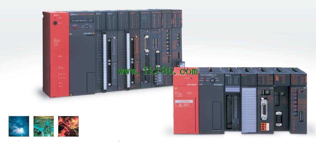
MITSUBISHI AJ71QBR11 Coaxial cable module MITSUBISHI AJ71QBR11
Brand:
MITSUBISHI
Name: Coaxial cable module
Model: AJ71QBR11
3C-2V/5C-2V coaxial cable.
Single bus.
PC inter network (management station / common station) / remote I/O network (remote control station).
How to choose MITSUBISHI PLC.
MITSUBISHI PLC options include the choice of MITSUBISHI PLC models, capacity, I/O module, power, etc..
MITSUBISHI PLC distribution I/O points and design MITSUBISHI PLC peripheral hardware circuit
Draw the I/O point of the PLC and the input / output device connection diagram or the corresponding table,
This part also can be carried out in second steps.
Design PLC peripheral hardware circuit.
Draw the electrical wiring diagram of the other parts of the system,
Including the main circuit and the control circuit does not enter the PLC, etc..
The electrical schematic diagram of the system composed of I/O PLC connection diagram and PLC peripheral electrical circuit diagram.
So far the system''s hardware electrical circuit has been determined.
...More relevant models >>>>
Name: Coaxial cable module
Model: AJ71QBR11
3C-2V/5C-2V coaxial cable.
Single bus.
PC inter network (management station / common station) / remote I/O network (remote control station).
How to choose MITSUBISHI PLC.
MITSUBISHI PLC options include the choice of MITSUBISHI PLC models, capacity, I/O module, power, etc..
MITSUBISHI PLC distribution I/O points and design MITSUBISHI PLC peripheral hardware circuit
Draw the I/O point of the PLC and the input / output device connection diagram or the corresponding table,
This part also can be carried out in second steps.
Design PLC peripheral hardware circuit.
Draw the electrical wiring diagram of the other parts of the system,
Including the main circuit and the control circuit does not enter the PLC, etc..
The electrical schematic diagram of the system composed of I/O PLC connection diagram and PLC peripheral electrical circuit diagram.
So far the system''s hardware electrical circuit has been determined.
3C-2V/5C-2V coaxial cable.
Single bus.
Remote I/O network (remote control station).
How to choose MITSUBISHI PLC.
MITSUBISHI PLC options include the choice of MITSUBISHI PLC models, capacity, I/O module, power, etc..
MITSUBISHI PLC distribution I/O points and design MITSUBISHI PLC peripheral hardware circuit
Draw the I/O point of the PLC and the input / output device connection diagram or the corresponding table,
This part also can be carried out in second steps MITSUBISHI AJ71QBR11 AJ71QBR11
Design PLC peripheral hardware circuit.
Draw the electrical wiring diagram of the other parts of the system,
Including the main circuit and the control circuit does not enter the PLC, etc..
The electrical schematic diagram of the system composed of I/O PLC connection diagram and PLC peripheral electrical circuit diagram MITSUBISHI AJ71QBR11.
So far the system''s hardware electrical circuit has been determined. A3VTS using the basic unit.
Relay output interface circuit of PLC
Working process: when the internal circuit output digital signal 1,
There is a current flowing through, the relay coil has a current, and then the normally open contact is closed,
Provide load current and voltage MITSUBISHI AJ71QBR11.
When the internal circuit outputs a digital signal 0, there is no current flowing through it,
The relay coil does not have a current, and the normally open contact is broken off,
A current or voltage that is disconnected from the load MITSUBISHI Coaxial cable module.
It is through the output interface circuit to the internal digital circuit into a signal to make the load action or not action MITSUBISHI Coaxial cable module.
When the programmer input programinto the user program memory,
Then CPU according to the function of the system (the system program memory to explain the compiler),
Translate the user program into PLC internally recognized by the user to compile the program.
I/O points is an important indicator of PLC MITSUBISHI Coaxial cable module.
Reasonable selection of I/O points can not only satisfy the control requirements of the system,
And the total investment of the system is the lowest.
The input and output points and types of PLC should be determined accordinng to the analog quantity and switch quantity of the controlled object,
Generally an input / output element to take up an input / output point AJ71QBR11.
Taking into account the future adjustment and expansion,
In general should be estimaated on the total number of points plus the amount of spare 20%~30% MITSUBISHI AJ71QBR11.
The following describes the centralized control system I/O points of the estimate.
...More relevant models >>>>
 Last one: MITSUBISHI Computer link module AJ71C24-S5
 next one: MITSUBISHI Coaxial cable module AJ72QBR15
Related download