
Home
>> Products
>> MITSUBISHI
>> A/QnA series PLC
>> High function module
>> Other high function modules
>> MITSUBISHI AD59MEM AD59 (-S1) data storage MITSUBISHI AD59MEM
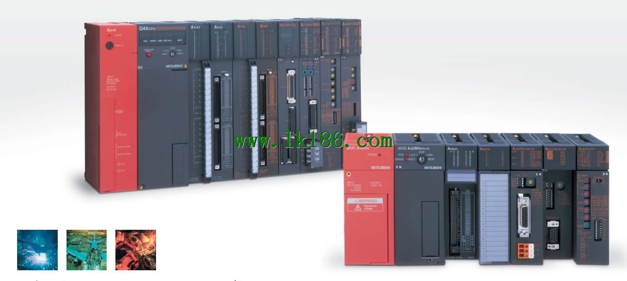
MITSUBISHI AD59MEM AD59 (-S1) data storage MITSUBISHI AD59MEM
Brand:
MITSUBISHI
Name: Memory card
Model: AD59MEM
SRAM capacity: 32K bytes.
AD59 (-S1) data storage.
On-line debugging is the process that will through the simulation debugging to further carry on the on-line unification to adjust.
On-line debugging process should be step by step,
From MITSUBISHI PLC only connected to the input device, and then connect the output device, and then connect to the actual load and so on and so on step by step.
If you do not meet the requirements, the hardware and procedures for adjustment.
Usually only need to modify the part of the program can be
...More relevant models >>>>
Name: Memory card
Model: AD59MEM
SRAM capacity: 32K bytes.
AD59 (-S1) data storage.
On-line debugging is the process that will through the simulation debugging to further carry on the on-line unification to adjust.
On-line debugging process should be step by step,
From MITSUBISHI PLC only connected to the input device, and then connect the output device, and then connect to the actual load and so on and so on step by step.
If you do not meet the requirements, the hardware and procedures for adjustment.
Usually only need to modify the part of the program can be
1 channels.
50/10kpps.
Count input signal: DC5/12/24V.
External input: DC5/12/24V.
Output: Transistor (open collector).
Output: DC12/24V, 0.1A/1 point, 0.8A/1 common.
47 point terminal station.
How to determine the input / output device of MITSUBISHI plc.
According to the control requirements of the system,
All input devices and output devices required for the determination of the system,
To determine the input / output device related to the MITSUBISHI PLC,
To determine the I/O PLC points MITSUBISHI AD59MEM AD59MEM
Detailed analysis of the process and work characteristics of the controlled object,
To understand the coordination between the controlled object machine, electricity and liquid,
The control requirements of the controlled object for MITSUBISHI PLC control system are put forward,
Determine the control program, to develop a design task book MITSUBISHI AD59MEM. Self service (IN, OUT): SI optical cable.
Other aspects (IN, OUT): SI optical cable.
Data link anomaly Bureau bypass.
Inter agency extension. Multi axis positioning controller.
Optical data communication line.
Program capacity: Max 60K step.
Input / output points: 1920 points MITSUBISHI AD59MEM.
When the switch is off, the diode does not emit light, and the transistor is not on the way. Internal circuit input signal.
It is through the input interface circuit to the external switch signal into PLC internal can accept the digital signal MITSUBISHI Memory card.
Photoelectric three levels: in the light of the light signal conduction, the degree of light signal and the intensity of the light signal MITSUBISHI Memory card.
The output signal has a linear relationship with the input signal in the linear operating region of the photoelectric coupler.
User program storage capacity: it is a measure of how much the user application can store the number of indicators.
Usually in words or K words as units. 16 bit binary number is a word,
Every 1024 words are 1K words MITSUBISHI Memory card. PLC to store instructions and data in words.
General logical operation instructions each account for 1 words. Timer / counter,
Shift instruction accounted for 2 words. Data operation instructions for 2~4.
The length of time required to execute the instruction, the length of the user''s program, the type of instruction, and the speed of the CPU execution are very significant,
Generally, a scanning process, the fault diagnosis time,
Communication time, input sampling and output refresh time is less,
The execution time is accounted for the vast majority of.
The photoelectric coupler is composed of two luminous two extreme tubes and a photoelectric transistor.
Light emittinng diode two: the input of a photo coupler and the change of electrical signal,
The light signal is generated by the light emitting diode, which is the same as the input signal AD59MEM.
The working process of the input interface circuit: when the switch is closed, the diode light,
The transistor is then guided to the internal circuit and input signal under the irradiation of the light MITSUBISHI AD59MEM.
...More relevant models >>>>
 Last one: MITSUBISHI Memory card interface module AD59-S1
 next one: MITSUBISHI Display module AD22-S1
Related download