
Home
>> Products
>> MITSUBISHI
>> A/QnA series PLC
>> CPU
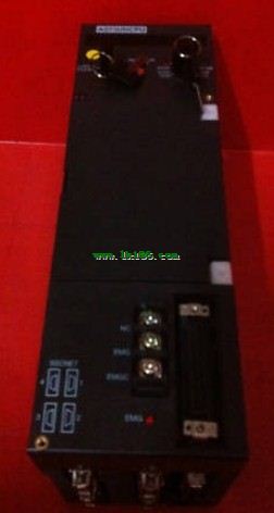
>> MITSUBISHI A273UHCPU cpu module A273UHCPU
MITSUBISHI A273UHCPU cpu module A273UHCPU
Brand:
MITSUBISHI
Name: cpu module
Model: A273UHCPU
...More relevant models >>>>
Name: cpu module
Model: A273UHCPU
Twisted pair cable.
Single bus.
Remote I/O station.
According to the control requirements of the system, using the appropriate design method to design MITSUBISHI PLC program.
Procedures to meet the requirements of system control as the main line,
Write one by one to achieve the control function or the sub task of the program,
Gradually improve the functions specified by the system MITSUBISHI A273UHCPU A273UHCPU
MITSUBISHI PLC initialization procedure. After MITSUBISHI PLC on power, the general need to do some of the initial operation,
In order to start making necessary preparations, to avoid the wrong operation of the system.
The main contents of the initialization program are: to some data area, counter and so on,
Data needed to restore some of the data area,
Set or reset some relays,
For some initial state display, etc MITSUBISHI A273UHCPU. . MITSUBISHI PLC hardware implementation
Hardware implementation is mainly for the control cabinet and other hardware design and field construction.
Design control cabinet and the operating table and other parts of the electrical wiring diagram and wiring diagram.
Electrical interconnection diagram of each part of the design system MITSUBISHI A273UHCPU.
According to the construction drawings of the site wiring, and carry out a detailed inspection.
Because the program design and hardware implementation can be carried out at the same time,
So the design cycle of the MITSUBISHI PLC control system can be greatly reduced MITSUBISHI cpu module. 3C-2V/5C-2V coaxial cable.
Double loop.
PC inter network (management station / common station) / remote I/O network (remote control station) MITSUBISHI cpu module.
How to choose MITSUBISHI PLC.
MITSUBISHI PLC options include the choice of MITSUBISHI PLC models, capacity, I/O module, power, etc..
MITSUBISHI PLC distribution I/O points and design MITSUBISHI PLC peripheral hardware circuit
Draw the I/O point of the PLC and the input / output device connection diagram or the corresponding table,
This part also can be carried out in second steps MITSUBISHI cpu module.
Design PLC periipheral hardware circuit A273UHCPU.
Draw the electrical wiring diagram of the other parts of the system,
Including the main circuit and the control circuit does not enter the PLC, etc..
The electrical schematic diagram of the system compoosed of I/O PLC connection diagram and PLC peripheral electrical circuit diagram MITSUBISHI A273UHCPU.
So far the system''s hardware electrical circuit has been determined.
...More relevant models >>>>
 Last one:
  next one:
 Related download