
Home
>> Products
>> MITSUBISHI
>> A/QnA series PLC
>> High function module
>> Other high function modules
>> AJ71ID2-R4 MITSUBISHI AJ71ID2-R4 Program 2 channel connection ID system module
AJ71ID2-R4 MITSUBISHI AJ71ID2-R4 Program 2 channel connection ID system module
Brand:
MITSUBISHI
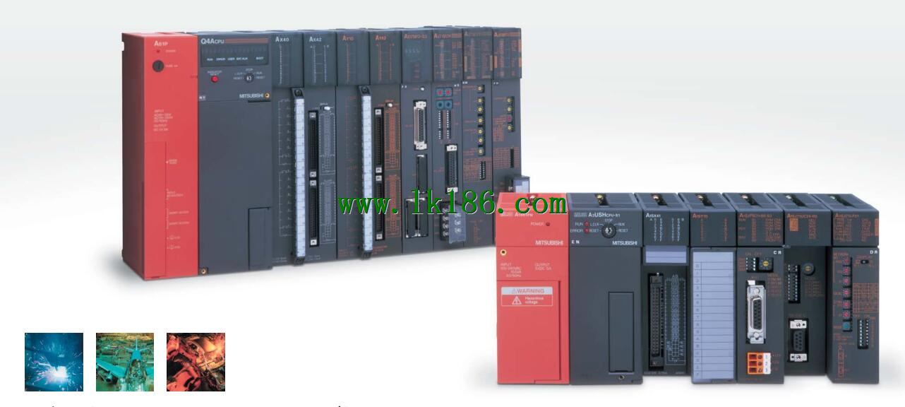
Name: ID system module
Model: AJ71ID2-R4
Bus connection.
Program 2 channel connection.
MITSUBISHI PLC detection, fault diagnosis and display and other procedures.
These procedures are relatively independent, generally in the basic completion of the program design and then add.
MITSUBISHI PLC protection and chain procedures.
Protection and chain is an indispensable part of the program, must be carefully considered.
It can avoid the control logic confusion caused by illegal operations.
...More relevant models >>>>
Name: ID system module
Model: AJ71ID2-R4
Bus connection.
Program 2 channel connection.
MITSUBISHI PLC detection, fault diagnosis and display and other procedures.
These procedures are relatively independent, generally in the basic completion of the program design and then add.
MITSUBISHI PLC protection and chain procedures.
Protection and chain is an indispensable part of the program, must be carefully considered.
It can avoid the control logic confusion caused by illegal operations.
Multi axis positioning controller.
Program capacity: Max 60K step.
Input / output points: 1920 points.
The length of time required to execute the instruction, the length of the user''s program, the type of instruction, and the speed of the CPU execution are very significant,
Generally, a scanning process, the fault diagnosis time,
Communication time, input sampling and output refresh time is less,
The execution time is accounted for the vast majority of MITSUBISHI AJ71ID2-R4 AJ71ID2-R4
The photoelectric coupler is composed of two luminous two extreme tubes and a photoelectric transistor.
Light emitting diode two: the input of a photo coupler and the change of electrical signal,
The light signal is generated by the light emitting diode, which is the same as the input signal MITSUBISHI AJ71ID2-R4.
The working process of the input interface circuit: when the switch is closed, the diode light,
The transistor is then guided to the internal circuit and input signal under the irradiation of the light.
When the switch is off, the diode does not emit light, and the transistor is not on the way. Internal circuit input signal.
It is through the input interface circuit to the external switch signal into PLC internal can accept the digital signal MITSUBISHI AJ71ID2-R4.
Photoelectric three levels: in the light of the light signal conduction, the degree of light signal and the intensity of the light signal MITSUBISHI ID system module.
The output signal has a linear relationship with the input signal in the linear operating region of the photoelectric coupler.
User program storage capacity: it is a measure of how much the user application can store the number of indicators MITSUBISHI ID system module.
Usually in words or K words as units. 16 bit binary number is a word,
Every 1024 words are 1K words. PLC to store instructions and data in words.
General logical operation instructions each account for 1 words MITSUBISHI ID system module. Timer / counter,
Shift instruction accounted for 2 words. Data operation instructions for 2~4. SRAM capacity: 32K bytes.
AD59 (-S1) data storage.
On-line debugging is the process that will through the simulation debugging to further carry on the on-liine unification to adjust AJ71ID2-R4.
On-line debugging process should be step by step,
From MITSUBISHI PLC only connected to the input device, and then connect the output device, and then connect to the actual load and so on and so on sttep by step MITSUBISHI AJ71ID2-R4.
If you do not meet the requirements, the hardware and procedures for adjustment.
Usually only need to modify the part of the program can be
...More relevant models >>>>
 Last one: MITSUBISHI ID system module AJ71ID1-R4
 next one: MITSUBISHI Communication module A70BDE-J71LP23GE
Related download