
Home
>> Products
>> MITSUBISHI
>> A/QnA series PLC
>> Network / serial communication module
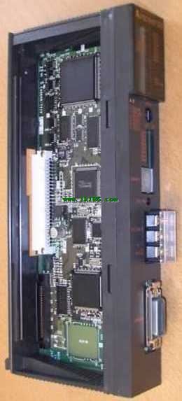
>> AJ71E71N-B5T MITSUBISHI AJ71E71N-B5T Control layer /MELSECNET/10 (H) is the middle layer of the whole network system, Network module
AJ71E71N-B5T MITSUBISHI AJ71E71N-B5T Control layer /MELSECNET/10 (H) is the middle layer of the whole network system, Network module
Brand:
MITSUBISHI
Name: Network module
Model: AJ71E71N-B5T
Ethernet network module 10BASE-T/10BASE5.
Control layer /MELSECNET/10 (H) is the middle layer of the whole network system,
Control network which is convenient and high speed processing data transmission between PLC, CNC and other control equipment.
As MELSEC control network MELSECNET/10,
With its good real-time performance, simple network settings, no procedures of the network data sharing concept,
As well as the redundant circuit and so on, has obtained the very high market appraisal,
The number of devices to reach the highest in japan,
In the world is also one of the few.
And MELSECNET/H not only inherited the excellent characteristics of MELSECNET/10,
Also makes the network real-time better, more data capacity,
Further adapt to the needs of the market.
...More relevant models >>>>
Name: Network module
Model: AJ71E71N-B5T
Ethernet network module 10BASE-T/10BASE5.
Control layer /MELSECNET/10 (H) is the middle layer of the whole network system,
Control network which is convenient and high speed processing data transmission between PLC, CNC and other control equipment.
As MELSEC control network MELSECNET/10,
With its good real-time performance, simple network settings, no procedures of the network data sharing concept,
As well as the redundant circuit and so on, has obtained the very high market appraisal,
The number of devices to reach the highest in japan,
In the world is also one of the few.
And MELSECNET/H not only inherited the excellent characteristics of MELSECNET/10,
Also makes the network real-time better, more data capacity,
Further adapt to the needs of the market.
ROM capacity: 32K bytes (max 15K step).
A2A, A2A-S1, A3A, A2N, A2N-S1, A3N storage box. MITSUBISHI PLC online debugging.
On-line debugging is the process that will through the simulation debugging to further carry on the on-line unification to adjust.
On-line debugging process should be step by step,
From MITSUBISHI PLC only connected to the input device, and then connect the output device, and then connect to the actual load and so on and so on step by step MITSUBISHI AJ71E71N-B5T AJ71E71N-B5T
If you do not meet the requirements, the hardware and procedures for adjustment.
Usually only need to modify the part of the program can be. BASIC program running.
RS-232 2 channel, RS-422 2 channel.
How to determine the input / output device of MITSUBISHI plc MITSUBISHI AJ71E71N-B5T.
According to the control requirements of the system,
All input devices and output devices required for the determination of the system,
To determine the input / output device related to the MITSUBISHI PLC,
To determine the I/O PLC points.
Detailed analysis of the process and work characteristics of the controlled object,
To understand the coordination between the controlled object machine, electricity and liquid,
The control requirements of the controlled object for MITSUBISHI PLC control system are put forward,
Determine the control program, to develop a design task book MITSUBISHI AJ71E71N-B5T. Input points: 32 points MITSUBISHI Network module.
Input voltage: DC12V/DC24V/AC12V/AC24V.
Current: 4mA (DC12V/AC12V), 8.5mA (DC24V/DC24V).
Response time: 30ms (DC12/24V) /35ms (AC12/24V).
16 points / a common end MITSUBISHI Network module.
50 point terminal station.
System program memory for storing system program,
Including management procedures, monitoring procedures, as well as the user program to do the compiler to compile the process of interpretation.
Read only memory. Manufacturers use, content can not be changed, power does not disappear MITSUBISHI Network module.
PLC selection with the development of PLC technology, more and more types of PLC products,
Function is becoming more and more perfect, and its application is more and more extensive.
Different series of different models of PLC has different performance, applicable occasions also have different emphasis,
Price also has a greater difference. Therefore PLC selection,
Under the premise of meeting the control requirements,
Should consider the best performance to price ratio, a reasonable choice of PLC.
Each scanning process. Focus on the input signal sampling. Focus on the output signal to refresh.
Input refresh process. When the input port is closed,
Program in the implementation phase, the input end of a new state, the new state can not be read.
Only when the program is scanned, the new state is read.
A scan cycle is divided into the input sample, the program execution, the output refresh.
The contents of the componentt image register are changed with the change of the execution of the program AJ71E71N-B5T.
The length of the scan cycle is determined by the three.
CPU the speed of executing instructions.
Time of instruction.
Instruction count.
Due to thhe adoption of centralized sampling MITSUBISHI AJ71E71N-B5T.
Centralized output mode.
There exist input / output hysteresis phenomena, i.e., the input / output response delay.
...More relevant models >>>>
 Last one:
  next one:
 Related download