
Home
>> Products
>> MITSUBISHI
>> A/QnA series PLC
>> High function module
>> Other high function modules
>> A80BDE-J61BT13 MITSUBISHI A80BDE-J61BT13
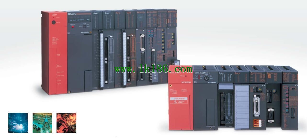
A80BDE-J61BT13 MITSUBISHI A80BDE-J61BT13
Brand:
MITSUBISHI
Name: Communication module
Model: A80BDE-J61BT13
...More relevant models >>>>
Name: Communication module
Model: A80BDE-J61BT13
Input and output points: 1024 points.
Input / output data points: 1024 points.
Program capacity: 14K.
Basic command processing speed (LD command) s:0.20.
Optical data communication line.
Each scanning process. Focus on the input signal sampling. Focus on the output signal to refresh.
Input refresh process MITSUBISHI A80BDE-J61BT13. When the input port is closed,
Program in the implementation phase, the input end of a new state, the new state can not be read A80BDE-J61BT13
Only when the program is scanned, the new state is read.
A scan cycle is divided into the input sample, the program execution, the output refresh.
The contents of the component image register are changed with the change of the execution of the program.
The length of the scan cycle is determined by the three MITSUBISHI A80BDE-J61BT13.
CPU the speed of executing instructions.
Time of instruction.
Instruction count.
Due to the adoption of centralized sampling.
Centralized output mode.
There exist input / output hysteresis phenomena, i.e., the input / output response delay.
User program storage capacity: it is a measure of how much the user application can store the number of indicators MITSUBISHI A80BDE-J61BT13.
Usually in words or K words as units. 16 bit binary number is a word,
Every 1024 words are 1K words. PLC to store instructions and data in words.
General logical operation instructions each account for 1 words. Timer / counter,
Shift instruction accounted for 2 words MITSUBISHI Communication module. Data operation instructions for 2~4. Multi axis positioning controller.
Optical data communication line MITSUBISHI Communication module.
Program capacity: Max 60K step.
Input / output points: 1920 points.
When the switch is off, the diode does not emit light, and the transistor is not on the way. Internal circuit input signal.
It is through the input interface circuit to the external switch signal into PLC internal can accept the digital signal MITSUBISHI Communication module.
Photoelectric three levels: in the light of the light signal conduction, the degree of light signal and the intensity of the light signal.
The output signal has a linear relationship with the input signal in the linear operating region of the photoelectric coupler.
User program storage capacity: it is a measure of how much the user application can store the number of indicators.
Usually in words or K words as units. 16 bit binary number is a word,
Every 1024 words are 1K words. PLC to store instructions and data in words.
General logical operation instructions each account for 1 words. Timer / counter,
Shift instruction accounted for 2 words. Data operation instructions for 2~4.
The length of time required to execute the instruction, the length of the user''s program, the type of instruction, and the speed of the CPU execution are very significant,
Generally, a scanning process, the fault diagnosis time,
Communication time, input sampling and output refresh time is less,
The execution time is accounted for the vast majority of.
The photoelectric coupler is composed of two luminous two extreme tubes and a photoelectric transistor.
Light emitting diodee two: the input of a photo coupler and the change of electrical signal,
The light signal is generated by the light emitting diode, which is the same as the input signal A80BDE-J61BT13.
The working process of the input interface circuit: when the switch is closed, the diode light,
The transistor is then guided to the internal circuit and input signal under the irradiation of the light MITSUBISHI A80BDE-J61BT13.
...More relevant models >>>>
 Last one: MITSUBISHI Communication module A80BDE-J61BT11
 next one: MITSUBISHI Communication module AJ71BH92
Related download