
Home
>> Products
>> MITSUBISHI
>> A/QnA series PLC
>> A/QnA series accessories
>> A6DIN2C MITSUBISHI A6DIN2C parts
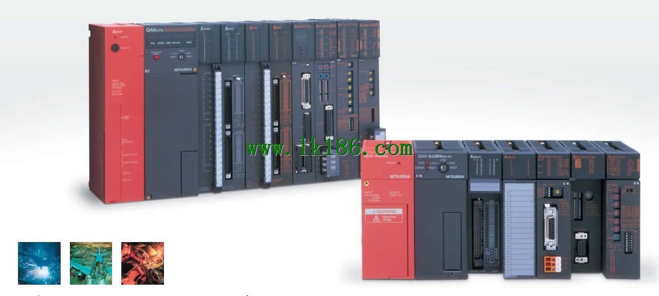
A6DIN2C MITSUBISHI A6DIN2C parts
Brand:
MITSUBISHI
Name: parts
Model: A6DIN2C
Adapter for mounting rails. CPU unit.
...More relevant models >>>>
Name: parts
Model: A6DIN2C
Adapter for mounting rails. CPU unit.
MITSUBISHI PLC hardware implementation
Hardware implementation is mainly for the control cabinet and other hardware design and field construction.
Design control cabinet and the operating table and other parts of the electrical wiring diagram and wiring diagram.
Electrical interconnection diagram of each part of the design system MITSUBISHI A6DIN2C.
According to the construction drawings of the site wiring, and carry out a detailed inspection A6DIN2C
Because the program design and hardware implementation can be carried out at the same time,
So the design cycle of the MITSUBISHI PLC control system can be greatly reduced. Cable 3M for the expansion of the floor, the expansion of a floor for every 1 units.Input voltage range: AC100 ~ 120V/AC200 ~ 240V MITSUBISHI A6DIN2C.
Output voltage: DC5/12V.
Output current: 2.3A/1.5A.
I/O points is an important indicator of PLC.
Reasonable selection of I/O points can not only satisfy the control requirements of the system,
And the total investment of the system is the lowest.
The input and output points and types of PLC should be determined according to the analog quantity and switch quantity of the controlled object,
Generally an input / output element to take up an input / output point MITSUBISHI A6DIN2C.
Taking into account the future adjustment and expansion,
In general should be estimated on the total number of points plus the amount of spare 20%~30% MITSUBISHI parts.
The following describes the centralized control system I/O points of the estimate.
Relay output interface circuit of PLC
Working process: when the internal circuit output digital signal 1,
There is a current flowing through, the relay coil has a current, and then the normally open contact is closed,
Provide load current and voltage MITSUBISHI parts.
When the internal circuit outputs a digital signal 0, there is no current flowing through it,
The relay coil does not have a current, and the normally open contact is broken off,
A current or voltage that is disconnected from the load MITSUBISHI parts.
It is through the output interface circuit to the internal digital circuit into a signal to make the load action or not action. GI fiber optic cable.
Dual loop for Q mode.
Remote I/O network (remote control station).
How to choose MITSUBISHI PLC.
MITSUBISHI PLC options include the choice of MITSUBISHI PLC models, capacity, I/O module, power, etc..
MITSUBISHI PLC distribution I/O points and design MITSUBISHI PLC peripheral hardware circuit
Draw the I/O point of the PLC and the input / output device connection diagram or the corresponding table,
This part also can be carried out in second steps.
Design PLC peeripheral hardware circuit A6DIN2C.
Draw the electrical wiring diagram of the other parts of the system,
Including the main circuit and the control circuit does not enter the PLC, etc..
The electrical schematic diagram of the system compoosed of I/O PLC connection diagram and PLC peripheral electrical circuit diagram MITSUBISHI A6DIN2C.
So far the system''s hardware electrical circuit has been determined.
...More relevant models >>>>
 Last one:
  next one:
 Related download