
A67RP MITSUBISHI A67RP
Brand:
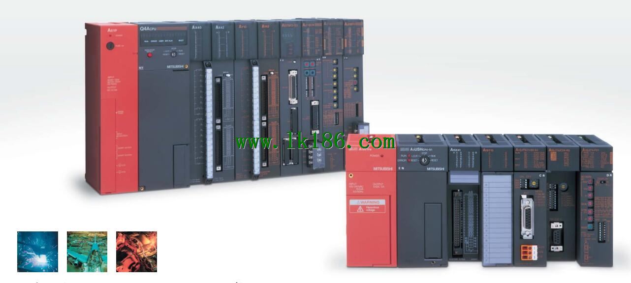
MITSUBISHI
Name: Power module
Model: A67RP
Input voltage range: DC110/125V.
Output voltage: DC5V.
Output current: 8A.
For Q4ARCPU.
The control module monitors the power supply, the error
CPU state,
And its own error state.
It sends out
Error signal a6raf and open the corresponding
Relay output.
I/O points is an important indicator of PLC.
Reasonable selection of I/O points can not only satisfy the control requirements of the system,
And the total investment of the system is the lowest.
The input and output points and types of PLC should be determined according to the analog quantity and switch quantity of the controlled object,
Generally an input / output element to take up an input / output point.
Taking into account the future adjustment and expansion,
In general should be estimated on the total number of points plus the amount of spare 20%~30%.
The following describes the centralized control system I/O points of the estimate.
...More relevant models >>>>
Name: Power module
Model: A67RP
Input voltage range: DC110/125V.
Output voltage: DC5V.
Output current: 8A.
For Q4ARCPU.
The control module monitors the power supply, the error
CPU state,
And its own error state.
It sends out
Error signal a6raf and open the corresponding
Relay output.
I/O points is an important indicator of PLC.
Reasonable selection of I/O points can not only satisfy the control requirements of the system,
And the total investment of the system is the lowest.
The input and output points and types of PLC should be determined according to the analog quantity and switch quantity of the controlled object,
Generally an input / output element to take up an input / output point.
Taking into account the future adjustment and expansion,
In general should be estimated on the total number of points plus the amount of spare 20%~30%.
The following describes the centralized control system I/O points of the estimate.
A3VTS with additional floor.
Switch volume control is designed to,
According to the current input combination of the switch quantity and the history of the input sequence,
So that PLC generates the corresponding switching output,
In order to make the system work in a certain order.
So, sometimes also known as the order control MITSUBISHI A67RP.
And sequential control is divided into manual, semi-automatic or automatic A67RP
And the control principle is decentralized, centralized and hybrid control three.
Each scanning process. Focus on the input signal sampling. Focus on the output signal to refresh.
Input refresh process. When the input port is closed,
Program in the implementation phase, the input end of a new state, the new state can not be read MITSUBISHI A67RP.
Only when the program is scanned, the new state is read.
A scan cycle is divided into the input sample, the program execution, the output refresh.
The contents of the component image register are changed with the change of the execution of the program.
The length of the scan cycle is determined by the three.
CPU the speed of executing instructions.
Time of instruction MITSUBISHI A67RP.
Instruction count.
Due to the adoption of centralized sampling.
Centralized output mode.
There exist input / output hysteresis phenomena, i.e., the input / output response delay.
System program memory for storing system program,
Including management procedures, monitoring procedures, as well as the user program to do the compiler to compile the process of interpretation MITSUBISHI Power module.
Read only memory MITSUBISHI Power module. Manufacturers use, content can not be changed, power does not disappear. Input points: 32 points.
Input voltage and current: 240V ~ 10mA AC100.
Input response time: 35ms.
16 point /1 a public side.
Output points: 24 points.
Output voltage: AC100 ~ 240V.
OFF leakage current: 3mA.
Output response time: 0 MITSUBISHI Power module. 5Hz+1ms.
Output type: bidirectional thyristor output.
8 point /1 a public side.
36 point terminal station.
With short circuit protection.
With the surge absorber.
Control solenoid valve required I/O points by the action principle of the solenoid valve can be known,
A single coil solenoid valve with PLC control to 2 input and 1 output,
A double coil solenoid valve requires 3 inputs and 2 outputs,
A button needs an input; a light sensitive switch needs 4 or 2 inputs,
A signal lamp needs 1 output, band switch,
Several bands are required for several inputs,
In general, a variety of position switches are required to take up 2 input points.
MITSUBISHI PLC is the main product in the production of MITSUBISHI motor in Dalian.
It uses a kind of programmable memory for its internal storage procedures,
Execute logic operation, sequence control, timing, counting and arithmetic operations, user oriented instruction,
And through digital or analog input / output control of various types of machinery or production process.
The number of I/O thyristor DC motor control required tube DC motor speed control system is the main form of DC speed regulation,
The thyristor rectifier unit is used to supply power to the DC motor.
PLC control of the DC drive system, the input of the PLC in addition to the main signal outside the signal,
We need to consider the switching signal, the fault signal transmission ddevice, brake signal and fan fault signal A67RP.
The output of the PLC mainly consider the speed command signal positive 1~3 level, 1~3 level, allowing reverse switching signal and brake open signal etc..
In general, a reversible DC drivee system controlled by PLC is approximately 12 input points and 8 output points,
An irreversible DC drive system requires 9 inputs and 6 output points MITSUBISHI A67RP.
...More relevant models >>>>
 Last one:
  next one:
 Related download