
Home
>> Products
>> MITSUBISHI
>> A/QnA series PLC
>> A/QnA series accessories
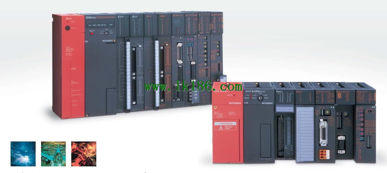
>> A2CCOM-TB MITSUBISHI A2CCOM-TB Enclosure
A2CCOM-TB MITSUBISHI A2CCOM-TB Enclosure
Brand:
MITSUBISHI
Name: Enclosure
Model: A2CCOM-TB
Terminal row for A2C
...More relevant models >>>>
Name: Enclosure
Model: A2CCOM-TB
Terminal row for A2C
SI-200/250 fiber optic cable.
Double loop.
MELSECNET (II) (Master / local station).
How to choose MITSUBISHI PLC.
MITSUBISHI PLC options include the choice of MITSUBISHI PLC models, capacity, I/O module, power, etc..
MITSUBISHI PLC distribution I/O points and design MITSUBISHI PLC peripheral hardware circuit
Draw the I/O point of the PLC and the input / output device connection diagram or the corresponding table,
This part also can be carried out in second steps MITSUBISHI A2CCOM-TB A2CCOM-TB
Design PLC peripheral hardware circuit.
Draw the electrical wiring diagram of the other parts of the system,
Including the main circuit and the control circuit does not enter the PLC, etc..
The electrical schematic diagram of the system composed of I/O PLC connection diagram and PLC peripheral electrical circuit diagram MITSUBISHI A2CCOM-TB.
So far the system''s hardware electrical circuit has been determined. Remote I/O controller, coaxial cable, coaxial loop system.
How to choose MITSUBISHI PLC.
MITSUBISHI PLC options include the choice of MITSUBISHI PLC models, capacity, I/O module, power, etc..
MITSUBISHI PLC distribution I/O points and design MITSUBISHI PLC peripheral hardware circuit
Draw the I/O point of the PLC and the input / output device connection diagram or the corresponding table,
This part also can be carried out in second steps MITSUBISHI A2CCOM-TB.
Design PLC peripheral hardware circuit MITSUBISHI Enclosure.
Draw the electrical wiring diagram of the other parts of the system,
Including the main circuit and the control circuit does not enter the PLC, etc MITSUBISHI Enclosure. .
The electrical schematic diagram of the system composed of I/O PLC connection diagram and PLC peripheral electrical circuit diagram.
So far the system''s hardware electrical circuit has been determined. Extension cable.
Length: 1000mm. A0J2 56.
Input / output unit 2
MITSUBISHI PLC program simulation debugging
The basic idea of program simulation debugging is,
In order to facilitate the form of simulation to generate the actual state of the scene,
Create the necessary environmental conditions for the operation of the program MITSUBISHI Enclosure.
Depending on the way the field signals are generated,
The simulation debugging has two forms of hardware simulation and software simulation. Enter 16 points.
Voltage and current: 6/14mA DC12/24V.
Response time: 0.2ms.
16 point /1 public end, 20 point terminal.
Detailed analysis of the process and work characteristics of the controlled object,
To understand the coordination between the controlled object machine, electricity and liquid,
The control requirements of the controlled object for MITSUBISHI PLC control system arre put forward,
Determine the control program, to develop a design task book A2CCOM-TB.
How to determine the input / output device of MITSUBISHI plc.
According to the control requirements of the system,
All input devices and output devicees required for the determination of the system,
To determine the input / output device related to the MITSUBISHI PLC,
To determine the I/O PLC points MITSUBISHI A2CCOM-TB.
...More relevant models >>>>
 Last one:
  next one:
 Related download