
Home
>> Products
>> MITSUBISHI
>> Ans/QnAs series PLC
>> Positioning control module
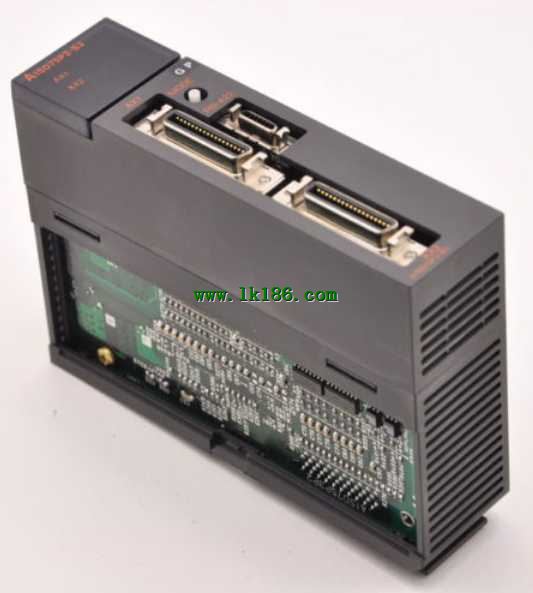
>> A1SD75P2-S3 MITSUBISHI Positioning control module A1SD75P2-S3
A1SD75P2-S3 MITSUBISHI Positioning control module A1SD75P2-S3
Brand:
MITSUBISHI
Name: Positioning control module
Model: A1SD75P2-S3
Axis of control: 2 axis linkage, 2 axis independence.
Interpolation function: 2 axis linear interpolation, 2 axis arc interpolation.
A1SD75 series components show the MITSUBISHI in the manufacture and design of CNC, frequency converter,
Integrated technical experience in servo system and PLC.
These components have a wealth of features that are sufficient to meet the highest requirements in the application of positioning control.
Up to 3 axis linkage operation,
In low cost motion control applications, this component can be used to control the operation of a multi - to 3 axis, which can be used to account for only one slot.
...More relevant models >>>>
Name: Positioning control module
Model: A1SD75P2-S3
Axis of control: 2 axis linkage, 2 axis independence.
Interpolation function: 2 axis linear interpolation, 2 axis arc interpolation.
A1SD75 series components show the MITSUBISHI in the manufacture and design of CNC, frequency converter,
Integrated technical experience in servo system and PLC.
These components have a wealth of features that are sufficient to meet the highest requirements in the application of positioning control.
Up to 3 axis linkage operation,
In low cost motion control applications, this component can be used to control the operation of a multi - to 3 axis, which can be used to account for only one slot.
Output type: transistor source / drain type.
Output points: 8 points.
Load voltage: DC5/12/24/48.
Load current: 2A.
Connection mode: terminal row.
Common public end points: 1.
Switching value, also known as logic, refers to only two values, 0 or 1, ON or OFF.
It is the most common control, it is the advantage of PLC control,
Is also the most basic application of PLC MITSUBISHI A1SD75P2-S3.
Switch volume control is designed to,
According to the current input combination of the switch quantity and the history of the input sequence,
So that PLC generates the corresponding switching output,
In order to make the system work in a certain order A1SD75P2-S3
So, sometimes also known as the order control.
And sequential control is divided into manual, semi-automatic or automatic MITSUBISHI A1SD75P2-S3.
And the control principle is decentralized, centralized and hybrid control three. Input and output points: 512 points.
Input / output data points: 8192 points.
Program capacity: 28k.
Basic command processing speed (LD command) S:0.075.
PLC in the program execution stage: according to the order of the user program order to store the order of each instruction,
After the corresponding operation and processing, the result is written to the output status register,
The contents of the output status register are changed with the execution of the program MITSUBISHI A1SD75P2-S3.
Output refresh phase: when all instructions are executed,
The output status register is sent to the output latch in the output refresh stage,
And through a certain way (relay, transistor or transistor) output, drive the corresponding output equipment MITSUBISHI Positioning control module MITSUBISHI Positioning control module. Input channel number: 2.
Output channel number: 1.
Occupy I/O points: 32.
A1S63ADA analog input / output combination components can be analog / digital / digital / analog conversion,
The input and output signals can be voltage or current,
Offset and gain can be set and stored MITSUBISHI Positioning control module.
The length of time required to execute the instruction, the length of the user''s program, the type of instruction, and the speed of the CPU execution are very significant,
Generally, a scanning process, the fault diagnosis time,
Communication time, input sampling and output refresh time is less,
The execution time is accounted for the vast majority of.
The response time of PLC is the interval between the time of the change of the external output signal of the PLC and thhe time of the change of the external output signal which is controlled by it,
Lag time, this is the time constant of the input circuit,
The time constant of the output circuit, the arrangement of the user statement and the usse of the instruction,
The cycle scan mode of PLC and the way of PLC to refresh the I/O and so on MITSUBISHI A1SD75P2-S3 A1SD75P2-S3.
This phenomenon is called the I/O delay time effect.
...More relevant models >>>>
 Last one: MITSUBISHI Positioning control module A1SD75P1-S3
 next one: MITSUBISHI Positioning control module A1SD75P3-S3
Related download