
Brand sort
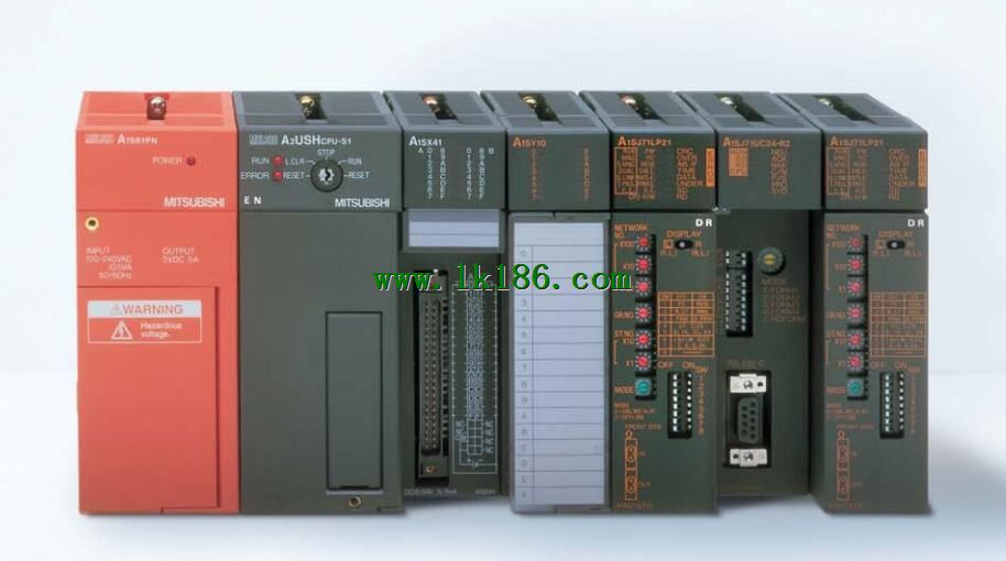
MITSUBISHI A1S62LS A1S62LS
Brand:
MITSUBISHI(Mitsubishi)
Country: JAPAN
Name: Positioning module
Model: A1S62LS
Market price: U.S.$ 0
(The following are the market open price not sales price!)
(The following are the market open price not sales price!)
 next one:
  Last one:
 MITSUBISHI A1S62LS
MITSUBISHI inverter FR-A740 series.
Voltage level: 3 phase 400V.
Frequency converter capacity: 37KW.
Frequency converter is the application of frequency conversion technology and micro electronics technology, by changing the motor operating power frequency mode to control the AC motor power control equipment MITSUBISHI A1S62LS.
The converter is composed of rectifier (AC), filter, inverter (DC), braking unit, driving unit, micro processing unit of the detection unit A1S62LS
Inverter by the internal IGBT to adjust the output power supply voltage and frequency,
According to the actual needs of the motor to provide the required power supply voltage, and then achieve the purpose of energy saving, speed control, in addition to the,
Inverter has a lot of protection functions, such as over current, over voltage, overload protection and so on MITSUBISHI A1S62LS. Protective film for 10.4 inch screen.
Scrub (frame: white), 5.
Applicable model: GT16. 3C-2V/5C-2V coaxial cable.
Double loop.
PC inter network (management station / station) / remote I/O network (remote control station) MITSUBISHI A1S62LS.
How to choose MITSUBISHI PLC.
MITSUBISHI PLC options include the choice of MITSUBISHI PLC models, capacity, I/O module, power, etc . .
MITSUBISHI PLC distribution I/O points and design MITSUBISHI PLC peripheral hardware circuit
Draw the I/O point of the PLC and the input / output device connection diagram or the corresponding table,
This part also can be carried out in second steps.
Design PLC peripheral hardware circuit.
Draw the electrical wiring diagram of the other parts of the system,
Including the main circuit and the control circuit does not enter the PLC, etc..
The electrical schematic diagram of the system composed of I/O PLC connection diagram and PLC peripheral electrical circuit diagram.
So far the system''s hardware electrical circuit has been determined. PLC station distance: 2Km.
Cable type: GI-62.5/125.
The function of the MELSECNET interface module is to connect the main CPU PLC to the MELSECNET data communication system.
As long as the switch on the component to set,
Can determine the CPU PLC is as the main station or in situ station.
There are two modules available for selection: one is the connection of the optical cable network and the network of the coaxial cable.
For a ANSCPU, up to only a piece of interface components can be inserted, A2ASCPU can be inserted 2.
The popularization and application of PLC programming has been developed rapidly in our country,
It has been widely used in all kinds of mechanical equipment and production process of electrical control devices,
All walks of life have emerged a large number of application of PLC transformation of the results of the equipment.
Understand the working principle of PLC, have the ability to design, debug and maintain the PLC control system,
Has become the basic requirements of modern industry for electrical technicians and engineering students.
The instruction list programming language is a programming language similar to assembly language mnemonic,
As well as assembly language by the operation code and the number of operations.
In the case of the computer for the PLC handheld programmer compile user program.
At the same time, the programming language of the instruction list corresponds to the ladder diagram programming language,
In PLC programming software can be converted to each other. Figure 3 is the instruction sheet corresponding to the ladder diagram of figure 2PLC.
The characteristics of instruction tablee programminng language is used to represent mnemonic operation function,
Easy to remember, easy to grasp;
In the handheld programmer on the keyboard using the mnemonic representation, easy to operate, can be programmed in computer;
There is a one-tto-oone correspondence between the ladder diagram and the ladder diagram A1S62LS A1S62LS. Its characteristics are basically consistent with the ladder diagram language.
A1S62LS Operation manual/Instructions/Model selection sample download link: /searchDownload.html?Search=A1S62LS&select=5
...more relevant model market price >>>>
Related products
MITSUBISHI
Temperature control module
A1S64TCTTBW-S1
Numer of channels: 4 channels.
Sensing
MITSUBISHI
Modular
A1SJ71J92-S3
JEMANET OPCN-1 interface unit master s
MITSUBISHI
Positioning control module
A1SD75M2
Axis of control: 2.
Interpolation functi
MITSUBISHI
High speed counting module
A1SD62D-S1
2 channels.
200/10kpps.
Count input sign
Related download