
Brand sort
A0J2PW MITSUBISHI A0J2PW
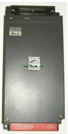
Brand:
MITSUBISHI(Mitsubishi)
Country: JAPAN
Name: Power module
Model: A0J2PW
Market price: U.S.$ 0
(The following are the market open price not sales price!)
(The following are the market open price not sales price!)
 next one:
  Last one:
 MITSUBISHI A0J2PW
Cable length: 30m.
Connection between serial communication unit and GOT.
Connection between a computer link unit and a GOT.
Applicable models: GT16, GT15, GT11, HandyGOT, GT10, GT27, GT25, GT23,, GT21. Memory format: EEPROM.
Number of steps: up to 16000 steps can be used.
Battery support: do not.
Method for writing and deleting: the device is installed on the PLC, and is written and deleted by the peripheral device A0J2PW Fiber length: 30 meters.
SSCNET III cable (long distance optical fiber, high bending life).
Joints for CN1A and CN1B. Length: 3.0m.
Specification: TB-FX round cable. Input type: DC input, positive public end / negative public end MITSUBISHI A0J2PW.
Input points: 32 points.
Enter the response time: 0 . 2ms the following.
Rated input voltage / current: DC24V/5mA.
External connection: 1 wire.
Fast connector type.
Simple wiring through quick connector.
Can be installed along the 6 direction.
MITSUBISHI PLC program simulation debugging
The basic idea of program simulation debugging is,
In order to facilitate the form of simulation to generate the actual state of the scene,
Create the necessary environmental conditions for the operation of the program MITSUBISHI A0J2PW.
Depending on the way the field signals are generated,
The simulation debugging has two forms of hardware simulation and software simulation. Screw terminal table type.
Voltage / current input module.
Number of channels: 4 channels.
Number of stations: 1 stops.
Station type: remote equipment station.
MITSUBISHI PLC hardware implementation
Hardware implementation is mainly for the control cabinet and other hardware design and field construction.
Design control cabinet and the operating table and other parts of the electrical wiring diagram and wiring diagram.
Electrical interconnection diagram of each part of the design system.
According to the construction drawings of the site wiring, and carry out a detailed inspection.
Because the program design and hardware implementation can be carried out at the same time,
So the design cycle of the MITSUBISHI PLC control system can be greatly reduced.
MITSUBISHI PLC online debugging.
On-line debugging is the process that will through the simulation debugging to furtherr carry on the on-line unification to adjust A0J2PW.
On-line debugging process should be step by step,
From MITSUBISHI PLC only connected to the input device, and then connect the output device, and then connect to the actual load and so on and so on stepp bby step A0J2PW.
If you do not meet the requirements, the hardware and procedures for adjustment.
Usually only need to modify the part of the program can be.
A0J2PW Operation manual/Instructions/Model selection sample download link: /searchDownload.html?Search=A0J2PW&select=5
...more relevant model market price >>>>
Related products
MITSUBISHI
AC input / relay output module
A0J2-E56AR
Input points: 32 points.
Input voltage a
MITSUBISHI
Connecting cable
A0J2-C10
Extension cale.
Length: 1000mm.
Related download