
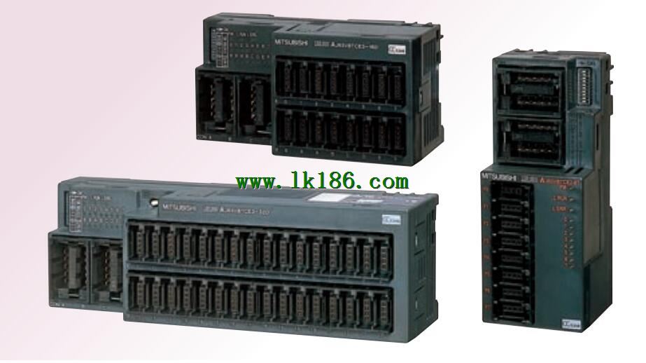
AJ65VBTCE3-8D Sensor connector type input module MITSUBISHI AJ65VBTCE3-8D
Analog channel: 8 channels.
Input / output (resolution): 0 ~ 4000.
Conversion speed: 100ms/8 channel.
Analog module installation.
Power supply: AC85 ~ 132V.
According to the control requirements of the system, using the appropriate design method to design MITSUBISHI PLC program AJ65VBTCE3-8D.
Procedures to meet the requirements of system control as tthe main line,
Write one by one to achieve the control function or the sub task of the program,
Gradually improve the functions specified by the system AJ65VBTCE3-8D.
MITSUBISHI PLC detection, fault diagnosis and display and other procedures.
These procedures are relatively independent, generally in the basic completion of the program design and then add.
Hardware simulation method is to use a number of hardware equipment to simulate the generation of the signal,
The signals are connected to the input end of the PLC system in a hard wired way, and the timeliness is strong AJ65VBTCE3-8D.
Software simulation method is in the MITSUBISHI PLC in the preparation of a set of simulation program,
The simulation provides the field signal, which is simple and easy to operate, but it is not easy to guarantee the timeliness MITSUBISHI AJ65VBTCE3-8D.
Simulation of the process of debugging, debugging method can be used to segment, and the monitoring function of programmer. Multi axis positioning controller.
Optical data communication line.
Program capacity: Max 60K step MITSUBISHI AJ65VBTCE3-8D.
Input / output points: 1920 points.
The length of time required to execute the instruction, the length of the user''s program, the type of instruction, and the speed of the CPU execution are very significant,
Generally, a scanning process, the fault diagnosis time,
Communication time, input sampling and output refresh time is less,
The execution time is accounted for the vast majority of MITSUBISHI AJ65VBTCE3-8D.
The photoelectric coupler is composed of two luminous two extreme tubes and a photoelectric transistor.
Light emitting diode two: the input of a photo coupler and the change of electrical signal,
The light signal is generated by the light emitting diode, which is the same as the input signal.
The working process of the input interface circuit: when the switch is closed, the diode light,
The transistor is then guided to the internal circuit and input signal under the irradiation of the light.
When the switch is off, the diode does not emit light, and the transistor is not on the way. Internal circuit input signal.
It is through the input interface circuit to the external switch signal into PLC internal can accept the digital signal.
Photoelectric three levels: in the light of the light signal conduction, the degree of light signal and the intensity of the light signal.
The output signal has a linear relationship with the input signal in the linear operating region of the photoelectric coupler.
User program storage capacity: it is a measure of how much the user application can store the number of indicators.
Usually in words or K words as units. 16 bit binary number is a word,
Every 1024 words are 1K words. PLC to store instructions and data in words.
General logical operation instructions each account for 1 words. Timer / counter,
Shift instruction accounted for 2 words. Data operation instructions for 2~4.
Input type: DC input, positive common end.
Input points: 8 points.
Enter the response time: 1.5ms the following.
Rated input voltage / current: DC24V/5mA.
External connectionn: 3 wire AJ65VBTCE3-8D.
Sensor connector type (E-CON type).
Using industry standard E-CON type.
Simple wiring through sensor connector.
When installing the module can choose to use the DIN guide rail or screw mounting.
3 wire sensor input.