
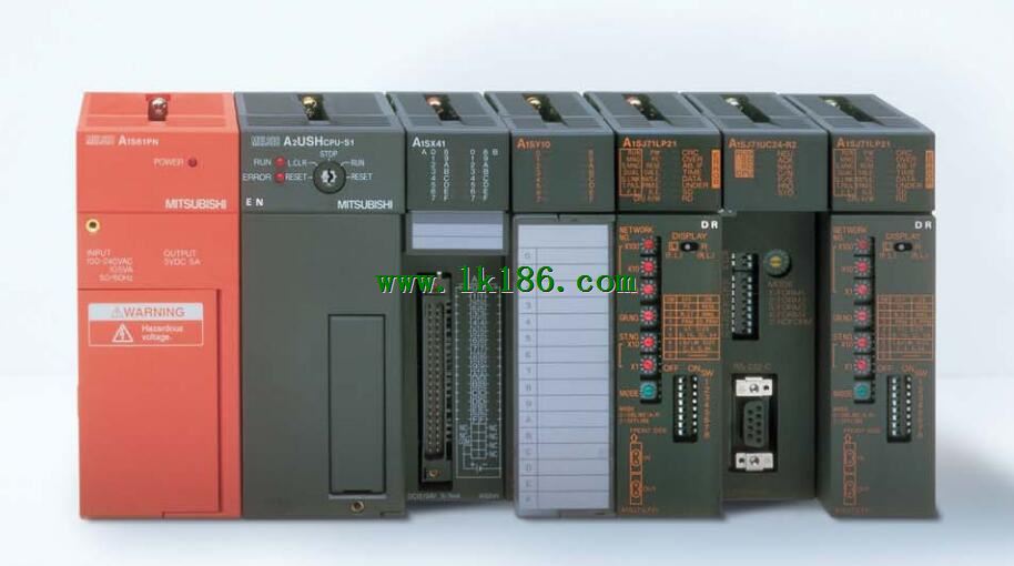
A1S62TCRTBW-S2 Temperature control module MITSUBISHI A1S62TCRTBW-S2
Cable 1.2m for the expansion of the floor, the expansion of a floor for every 1 units.Adapter for mounting rails. CPU unit.
Number of channels: 2 channels.
Sensing method and temperature range: PT100.
A1S64TC series component is a kind of temperature controller combined with ANS series CPU A1S62TCRTBW-S2.
Components with temperature measurement input and built-in PPID algorithm control output, can be used in a variety of temperature control occasions.
Each component controls up to 4 loops at most.
Thermocouple input or PT100 3 wire temperature sensor input A1S62TCRTBW-S2.
Control output switching signal for the output of the transistor.
BW is a signal with broken line detection function. Cable length 3M; used in A6TE2-16SRN.DC input points: 64 points.
Input voltage and current: 4/9mA, DC12/24V A1S62TCRTBW-S2.
Response time: 107ms.
Positive pole sharing.
16 point /1 a public side.
Output points: 64 points.
Output voltage and current: DC12/24V, 100mA/1 point, 2A/1 common end.
Response time: (2I/O update time * 5) Ms.
32 point /1 a public side.
Output form: transistor output, leakage type MITSUBISHI A1S62TCRTBW-S2.
40 pin connector x 4.
Number of stations: 4 stops.
Compact remote I/O unit.
According to the control requirements of the system, using the appropriate design method to design MITSUBISHI PLC program.
Procedures to meet the requirements of system control as the main line,
Write one by one to achieve the control function or the sub task of the program,
Gradually improve the functions specified by the system MITSUBISHI A1S62TCRTBW-S2.
MITSUBISHI PLC detection, fault diagnosis and display and other procedures.
These procedures are relatively independent, generally in the basic completion of the program design and then add MITSUBISHI A1S62TCRTBW-S2.
Hardware simulation method is to use a number of hardware equipment to simulate the generation of the signal,
The signals are connected to the input end of the PLC system in a hard wired way, and the timeliness is strong.
Software simulation method is in the MITSUBISHI PLC in the preparation of a set of simulation program,
The simulation provides the field signal, which is simple and easy to operate, but it is not easy to guarantee the timeliness.
Simulation of the process of debugging, debugging method can be used to segment, and the monitoring function of programmer. Category: Master station.
Transfer speed: 125kbps/250kbps/500kbps/1Mbps.
Transmission line form: bus system.
Total distance: 125kbps:1000m/250kbps:800m/500kbps:480m/1Mbps:240m.
The maximum connection units: 32.
Total points: input + output <=2048 point.
MITSUBISHI PLC detection, fault diagnosis and display and other procedures.
These procedures are relatively independent, generally in the basic completion of the proggram design and then add A1S62TCRTBW-S2.
MITSUBISHI PLC protection and chain procedures.
Protection and chain is an indispensable part of the program, must be carefully considered.
It can avoid the control logic confusion caused by illegal operations.