
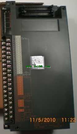
A0J2-E28DT MITSUBISHI A0J2-E28DT DC input / transistor output module
Output type: transistor output, drain type.
Output points: 32 points.
OFF leakage current: 0.25mA.
Output protection function.
Rated load voltage / current: DC24V/DC24V/0.1A.
External connection: 1 wire.
Fast connector type.
Simple wiring through quick connector.
Can be installed along the 6 direction A0J2-E28DT.
MITSUBISHI PLC pprogram simulation debugging
The basic idea of program simulation debugging is,
In order to facilitate the form of simulation to generate the actual state of the scene,
Create the necessary environmental conditions for the operation of the program A0J2-E28DT.
Depending on the way the field signals are generated,
The simulation debugging has two forms of hardware simulation and software simulation. 8 slots.
No need to install power A0J2-E28DT.
For QnA/A series.
Switch volume control is designed to,
According to the current input combination of the switch quantity and the history of the input sequence,
So that PLC generates the corresponding switching output,
In order to make the system work in a certain order MITSUBISHI A0J2-E28DT.
So, sometimes also known as the order control.
And sequential control is divided into manual, semi-automatic or automatic.
And the control principle is decentralized, centralized and hybrid control three.
Each scanning process. Focus on the input signal sampling. Focus on the output signal to refresh MITSUBISHI A0J2-E28DT.
Input refresh process. When the input port is closed,
Program in the implementation phase, the input end of a new state, the new state can not be read.
Only when the program is scanned, the new state is read.
A scan cycle is divided into the input sample, the program execution, the output refresh MITSUBISHI A0J2-E28DT.
The contents of the component image register are changed with the change of the execution of the program.
The length of the scan cycle is determined by the three.
CPU the speed of executing instructions.
Time of instruction.
Instruction count.
Due to the adoption of centralized sampling.
Centralized output mode.
There exist input / output hysteresis phenomena, i.e., the input / output response delay.
System program memory for storing system program,
Including management procedures, monitoring procedures, as well as the user program to do the compiler to compile the process of interpretation.
Read only memory. Manufacturers use, content can not be changed, power does not disappear.
Input points: 16 points.
Input voltage and current: 3/7mA DC12/24V.
Input response time: 10ms.
16 point /1 a public side.
Positive pole sharing.
Output points: 12 points.
Output voltage: DC12V/24V.
OFF leakage current: 0.1mA.
Output response time: 2ms.
Output type: transistor output.
8 point /1 a public end, 4 point /1 a public end.
36 point terminal station.
With the surge absorber.
Control solenoid valve required I/O points by the action principle of the solenoid valve can be known,
A single coil solenoid valve with PLC control to 2 input and 1 output,
A double coil solenoid valve requires 3 inputs and 2 outputs,
A button needs an input; a light sensitive switch needs 4 or 2 inputs,
A signal lamp needs 1 output, band switch,
Several bands are required for several inputs,
In general, a variety of position switches are required to take up 2 input points.
MITSUBISHI PLC is the main product in the production of MITSUBISHI motor in Dalian.
It uses a kind of programmable memory for its internal storage procedures,
Execute logic operation, sequence control, timing, counting and arithmetic operations, user oriented instruction,
And through digital or analog input / output control of various types of machinery or production process.
The number of I/O thyristor DC motor control required tube DC motor speed control system is the main form of DC speed regulation,
The thyristor rectifier unit is used to supply power to the DC motor.
PLC control of the DC drive system, the input of the PLC in addition to the main signal outside the signal,
We need to consider the switching signal, the fault signal transmission device, brake signal and fan fault signal.
The output of the PLC mainly consider the speed command signal positive 1~3 level, 1~3 level, allowwing reverse switching signal and brake open signal etc A0J2-E28DT..
In general, a reversible DC drive system controlled by PLC is approximately 12 input points and 8 output points,
An irreversible DC drive system requires 9 inputs and 6 output points.