
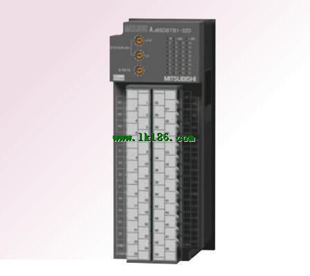
AJ65DBTB1-32DT1 MITSUBISHI AJ65DBTB1-32DT1 Output protection function: No
Type of input: DC leakage.
Input points: 64 points.
Input voltage: 12/DC24.
Input current: 2/5mA.
Connection mode: terminal row.
Common common point: 32.
Functional block diagram language is a kind of PLC programming language, which is similar to digital logic circuit.
The function module is used to represent the function of the module,
Different function modules have different functions AJ65DBTB1-32DT1.
Functional module figure programming language features: functional block diagram programming language is characterized by a functional module for the unit,
Analysis and understanding of the control scheme is simple and easy: function module is to use graphical form of expression,
Intuitive, for a digital logic circuit based on the design of the staff is very easy to master the programming;
Control system with complex scale and complex control logic,
Because the function module diagram can clearly express the function relation, the programming debugging time is greatly reduced AJ65DBTB1-32DT1 AJ65DBTB1-32DT1. 5 slots.
To install the power supply.
For QnA/A series MITSUBISHI AJ65DBTB1-32DT1.
Switch volume control is designed to,
According to the current input combination of the switch quantity and the history of the input sequence,
So that PLC generates the corresponding switching output,
In order to make the system work in a certain order.
So, sometimes also known as the order control MITSUBISHI AJ65DBTB1-32DT1.
And sequential control is divided into manual, semi-automatic or automatic.
And the control principle is decentralized, centralized and hybrid control three.
Each scanning process. Focus on the input signal sampling. Focus on the output signal to refresh MITSUBISHI AJ65DBTB1-32DT1.
Input refresh process. When the input port is closed,
Program in the implementation phase, the input end of a new state, the new state can not be read.
Only when the program is scanned, the new state is read.
A scan cycle is divided into the input sample, the program execution, the output refresh.
The contents of the component image register are changed with the change of the execution of the program.
The length of the scan cycle is determined by the three.
CPU the speed of executing instructions.
Time of instruction.
Instruction count.
Due to the adoption of centralized sampling.
Centralized output mode.
There exist input / output hysteresis phenomena, i.e., the input / output response delay.
System program memory for storing system program,
Including management procedures, monitoring procedures, as well as the user program to do the compiler to compile the process of interpretation.
Read only memory. Manufacturers use, content can not be changed, power does not disappear.
Input type: DC input, positive public end / negative public end.
Input points: 16 points.
Enter the response time: 10ms the following.
Rated input voltage / current: DC24V/5mA.
Output form: transistor output, leakage type.
Output points: 16 points.
OFF leakage current: 0.1mA.
Output protection function: No.
Rated load voltage / current: DC24V/DC24V/0.5A.
A2C shape terminal.
Type of input and output terminal.
Shape and A2C input and output modules are identical (same mounting dimensions),
Machining and installing holes are not required.